MAKE : CREATIVE LAB
MODEL NO:-CLFM-06
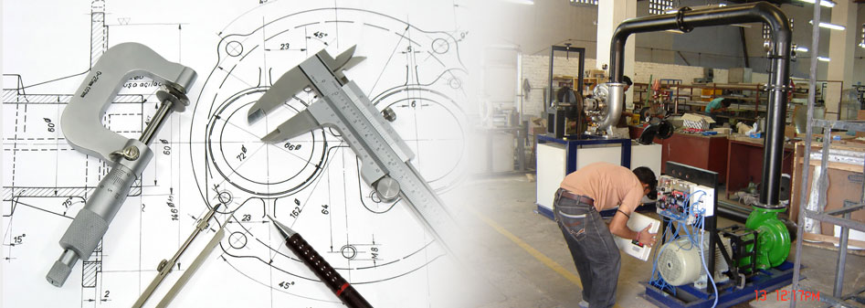
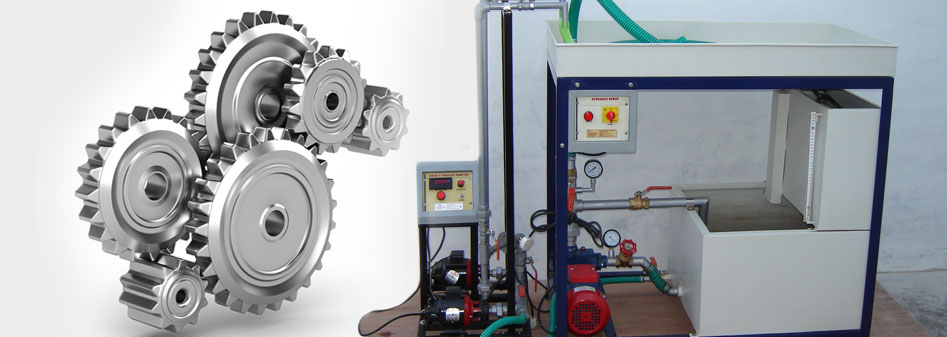
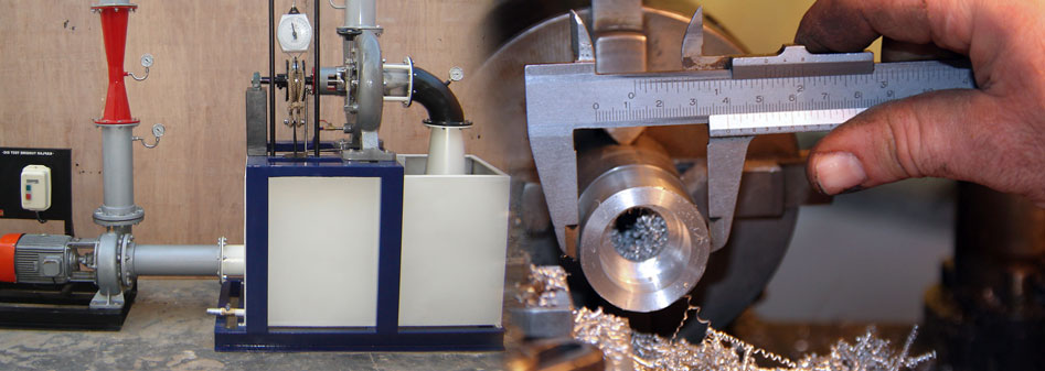
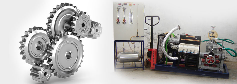
DESCRIPTION :
The set up consists of a ½” bend and elbow, a sudden expansion & sudden contraction fitting from 15mm to 25mm, ball valve and gate valve. Pressure tapings are provided at inlet and outlet of these fittings under test. A differential manometer fitted in the line gives pressure loss of individual fittings. Present set-up is self-contained water re-circulating unit, provided with a sump tank and a centrifugal pump etc. Flow control valve and by-pass valve are fitted in water line to conduct the experiment on different flow rates. Flow rate of water is measured with the help of measuring tank and stop watch.
EXPERIMENTATION:
To determine loss of head in the fittings at various water flow rates.
To measure the loss coefficient for the pipe fittings.
UTILITIES REQUIRED:
Water Supply (Initial Fill)
Drain.
Electricity 0.5 kW, 220V AC, Single Phase.
Floor Area 1.5 x 0.75 m.
TECHNICAL DETAIL
Manometer Fluid : Mercury (Hg) - 250 gm
Sudden Enlargement : From 15mm to 25mm
Sudden Contraction: From 25mm to 15mm.
Bend : ½”
Elbow : ½”
Ball valve : ½”
Gate valve : ½”
Water Circulation: FHP Pump, Crompton make.
Flow Measurement : Using Measuring Tank with Piezometer, Capacity 25 Ltrs.
Pressure Drop Measurement: Differential Manometer
Sump Tank : Capacity 50 Ltrs.
Stop Watch : Electronic.
Control Panel Comprises of :
Standard make On/Off Switch, Mains Indicator, etc.
Instruction Manual : An ENGLISH instruction manual will be provided along with the Apparatus Tanks will be made of Stainless Steel.
The whole set-up is well designed and arranged in a good quality painted structure.
|