logo
 
left right
shadow
STUDY OF PRESSURE MEASUREMENT MAKE :CREATIVE LAB MODEL NO:-CLFM-24
DESCRIPTION :
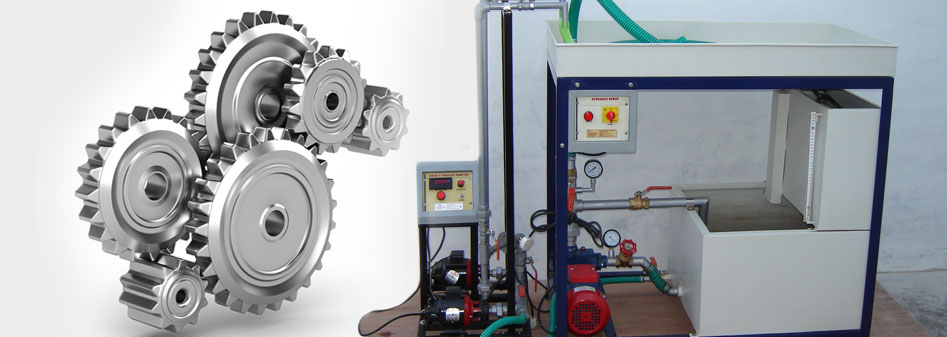
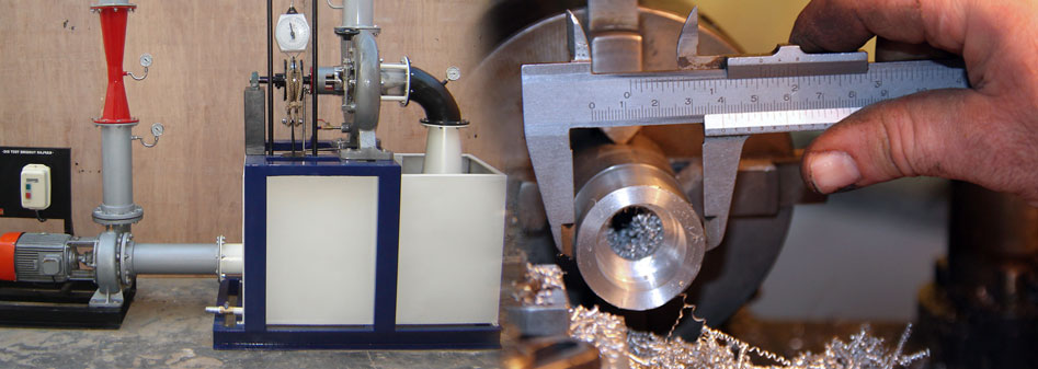
The set-up consists of different pressure measurement devices fitted in a pipe line, in which an Orifice is  fitted to create the pressure difference. Present set-up is self-contained water re-circulating unit, provided with a sump tank and a centrifugal pump etc. Flow control valve and by-pass valve are fitted in water line.
EXPERIMENTATION:
To demonstrate the working of different pressure measuring devices.
To measure the pressure and pressure difference by pressure gauge, single column manometer, UTube manometer & Inclined tube manometer.
UTILITIES REQUIRED :
Electricity Supply:  Single phase, 220 VAC, 50 Hz, 5-15 amp. Combined socket with earth
connection.
Water Supply (Initial fill)
Floor Drain required.
Floor Area Required:   1.5 m x 0.75 m 
Mercury (Hg) for manometer (750 gm).
TECHNICAL DETAILS:
Single Well Manometer: Single Tube Type.
Differential Manometer: U Tube Type.
Sensitive Manometer. : Inclined Tube Type
Pressure Gauge. : Bourdon Type
Water Circulation: FHP Pump, Champion makes.
Sump Tank: Capacity 60 Ltrs.
Control Panel Comprises of:
Standard make On/Off Switch, Mains Indicator, etc.
Instruction Manual: An ENGLISH instruction manual will be provided along
With the Apparatus Tanks will be made of Stainless Steel.
The whole set-up is well designed and arranged in a good quality painted structure.


BEND METER TEST RIG MAKE : CREATIVE LAB MODEL NO:-CLFM-25
DESCRIPTION :
The apparatus consists of a pipeline that contains one Bend meter. The pressure tapings from the Bend meter is taken to differential manometer to measure pressure difference. Present set-up is self-contained water re-circulating unit, provided with a sump tank and a centrifugal pump etc. Flow control valve and by-pass valve are fitted in water line to conduct the experiment on different flow rates. Flow rate of water is measured with the help of measuring tank and stop watch.
EXPERIMENTATION:
To demonstrate the use of Bend meter as flow meter.
To determine co-efficient of discharge for given Bend meter.
UTILITIES REQUIRED :
Electricity supply: Single Phase, 220 VAC, 50 Hz, 5-15 amp combined socket with earth connection.
Water Supply (Initial Fill).
Floor Drain required.
Floor Area required:  1.5 m x 0.75 m
Mercury (Hg) for manometer (250 gm).
TECHNICAL DETAILS :
Bend meter  : Material Stainless steel Compatible to 1” Dia. Pipe.
Water Circulation : FHP Pump, Crompton make
Flow Measurement : Using Measuring Tank (Capacity 25 Ltrs. (approx.) and Electronic Stop Watch
Sump Tank : Capacity 50 Ltrs. (approx.)
Control Panel Comprises of : Standard make On/Off Switch, Mains Indicator, etc.
Instruction Manual : An ENGLISH instruction manual will be provided along with the Apparatus Tanks will be made of Stainless Steel.
The whole set-up is well designed and arranged in a good quality painted structure.


FLUID PROPERTIES HYDROSTATIC BENCH
Description:
The Properties of Fluids and Hydrostatics Bench are designed to demonstrate the properties of fluids and their behavior under hydrostatic conditions (fluid at rest). This allows students to develop an understanding and knowledge of a wide range of fundamental principles and techniques, before studying fluids in motion. A variety of measuring devices is incorporated, either fastened to the back of the bench or freestanding. Water is stored in a stainless steel tank situated at the base of the unit. The water can be transferred by centrifugal pump, either to an elevated open storage tank connected to a number of glass tubes for free surface studies.
Experimentation:
Universal hydrometer and hydrometer jars
Falling sphere viscometers free surface tubes
Bourdon gauge 
U-tube manometer
Hydrostatic pressure apparatus 
Capillary tube apparatus 
Metacentric height apparatus 
Utilities Required:
Electricity supply: Single Phase, 220 V AC, 50 Hz, 5-15 amp combined socket with earth connection. Earth voltage should be less than 5 volts. 
Water Supply: Initial Fill 
Floor Drain. 
Floor Area: 1.75 m x 1.75 m.
Technical Details:
Universal Hydrometer : Range 0.70 to 2.00 sub-divided in 0.01 intervals
Falling Sphere Viscometer : 40mm tube diameter
Hydrostatic Pressure Apparatus : Comprises counter-balanced precision quadrant. Pivoted on knife edges at its centre of arc.
Thermometer : Range -1000C to +5000C
Tanks will be made of Stainless Steel.
An ENGLISH instruction manual consisting of experimental procedures, block diagram etc. will be provided along with the Apparatus
The whole set-up is well designed and arranged on a rigid structure painted with industrial PU Paint.
 

CAVITATION APPARATUS MAKE: CREATIVE LAB MODEL NO:CLFM-15
DESCRIPTION 
The apparatus  has  been  designed  to  demonstrate  the phenomenon of cavitation. The present set-up consists of a  test  section  made  of  Acrylic  having  conversion  and diversion  section.  Pressure tapings  at  appropriate position  are  provided.  This  test  section  is  having one control valve at upstream side to regulate the water flow rate. Two pressure gauges are connected to these taping which give  the  pressure  readout  at  the  time  of  flowpassing through this test section.  Present set-up is self-contained water re-circulating unit, provided with a sump tank, centrifugal pump etc. Water is  pumped  by  means  of  centrifugal  pump  and  passing through  the  test  section,  it  returns  back  to  the  sump which make the system re-circulating type. Flow of water is diverted either  to  measuring  tank  or  sump  tank  with the means of a flow diverter, when needed. Flow control valve and by-pass valve are fitted in water line to conduct the experiment on different flow rates. Flow rate of water is measured with  the  help  of  measuring  tank  with piezometer  and  stopwatch.  The supplied set-up  is complete in all respect. Only water supply and electricity supply is to be provided by the end user for running the set-up.
EXPERIMENTATION
To observe the phenomenon of cavitation. 
To compare the theoretical and actual pressures at cavitation condition.
UTILITIES REQUIRED
Electricity supply: Single Phase, 220 V AC, 50 Hz, 5-15 Amp.  combined socket with earth connection. 
Earth voltage would be less than 5 volts.
Water Supply: Initial Fill. 
Floor Drain Required.
Floor Area Required: 1.5 m x 1.0 m.
TECHNICAL DETAIL
Floor Area Required: 1.5 m (L) x 1 m. (W) 
Test Section : Material Acrylic/Poly Carbonate 
Pressure Gauge : 0-5 kg/cm2 
Vacuum Gauge : 0-760 mmHg 
Water Circulation: Pump would made from standard company 
Flow Measurement: Measuring Tank (Capacity : 50 liters) & Electronic Stop Watch. 
Sump Tank : Capacity : 60 liters 
Control Panel would comprise of : 
Standard make On/Off Switch, Mains Indicator, etc. 
Apparatus Tanks will be made of Stainless Steel. 
Apparatus would be capable of finding cavitation phenomena also it will be able to compare the theoretical and actual pressures at cavitation condition. 

SUBMERSIBLE PUMP TEST RIG MAKE : CREATIVE LAB MODEL NO:CLFM-46
DESCRIPTION:
The present Submersible Pump Test Rig is a self-contained unit operated on closed circuit basis containing a sump tank. The set-up consists of a Submersible Pump, which is mounted horizontally with sump tank. Flow of fluid is measured by using measuring tank and stop watch.
EXPERIMENTATION:
To determine total head, pump output, overall efficiency and pump efficiency of the submersible pump.
To plot Graph
Head vs Discharge
Pump efficiency vs Discharge
Pump HP vs Discharge.
UTILITIES REQUIRED :
Electricity Supply: Single Phase, 220 VAC, 50 Hz, 5-15 amp combined socket with earth connection.
Water Supply (Initial Fill).
Floor Drain required.
Floor Area Required:  1.5m x 0.75m
TECHNICAL DETAILS :
Pump : Submersible, Capacity 1 HP.
Medium Flow : Clear Water.
Sump Tank : Capacity 120 Ltrs.
Flow Measurement : Using Measuring Tank (Capacity 90 Ltrs.) & Electronic Stop Watch
Pressure Gauge : Bourdon type
Control Panel Comprises of :
Energy measurement : Energy meter Electronic, L&T make.
MCB : For overload protection.
Standard make On/Off Switch, Mains Indicator, etc.
Instruction Manual : An ENGLISH instruction manual will be provided along
with the Apparatus Tanks will be made of Stainless Steel.
The whole set-up is well designed and arranged in a good quality painted structure.


Prev   1  2  3  4  5  6   Next
SUBMERSIBLE PUMP TEST RIG MAKE : CREATIVE LAB MODEL NO:CLFM-46    CAVITATION APPARATUS MAKE: CREATIVE LAB MODEL NO:CLFM-15    FLUID PROPERTIES HYDROSTATIC BENCH    BEND METER TEST RIG MAKE : CREATIVE LAB MODEL NO:-CLFM-25    STUDY OF PRESSURE MEASUREMENT MAKE :CREATIVE LAB MODEL NO:-CLFM-24    
Categories
  HIGHWAY ENGINEERING LAB
 ADVANCED COMMUNICATION LAB
 ANALYTICAL LAB EQUIPMENT
 APPLIED MECHANICS LAB
 AUTOMATION MANUFACTURING LAB
 CHEMICAL REACTION ENGINEERING LAB
 CIVIL ENGINEERING LAB
 CIVIL LAB ALL IN ONE
 CIVIL LAB EQUIPMENTS
 CONCRETE LAB
 CORE LAB
 ELECTRICAL ENGINEERNG LAB EQUIPMENTS
 ELECTRONICS ENGINEERING LAB EQUIPMENTS
 ELECTRONICS LAB
 ENVIRONMENT LAB
 ENVIRONMENTAL ENGINEERING LAB
 FLUID MACHINERY LAB
 FLUID MECHANICS LAB
 GEOLOGY LAB
 GEOTECHNICAL ENGINEERING LAB
 HEAT TRANSFER LAB
 HYDRAULIC BENCH & ACCESSORIES
 IC ENGINE LAB BL
 MANUFACTURING PROCESSES LAB
 MASS TRANSFER LAB
 MATERIAL TESTING & CONCRETE LAB
 MATERIAL TESTING LAB
 MECHANICAL OPERATION LAB
 MEDICAL LAB EQUIPMENTS
 METALLURGICAL & MATERIAL SCIENCE LAB
 MOMENTUM TRANSFER LAB
 MONENTUM TRANSFER LAB
 PETROLEUM TESTING LAB
 PHYSICS LAB
 PHYSICS LAB
 PROCESS CONTROL & INSTRUMENTATION LAB
 PRODUCTION LAB
 REFRIGERATION & AIR CONDITIONING LAB
 STRENGHT OF MATERIAL LAB
 STRUCTURE LAB
 SURVEY LAB
 SURVEYING & GEOMATICS LAB
 THEORY OF MACHINE LAB
 THERMODYNAMICS LAB
 TRANSPORTATION & HIGHWAY ENGINEERING LAB
 WORKSHOP
 
Follow us on
facebook twitter in  
 
bottom
 
Home About us Products Enquiry Contact us